Description
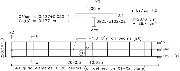
A simply supported composite beam – steel section and concrete slab – loaded with a uniformly distributed load.
All beams and elements in this space model are defined on the X1-X2 global plane. Beam offsets are used to place the steel section below the slab, thereby generating the increased moment-of-inertia of the composite section. Note that the structure must be defined as a space model in order to specify X3 offsets.
Geometry
Modulus of Elasticity: Concrete: 300,000 t/m2 Steel: 2,100,000 t/m2
Loads
Beam load: FX3 = -1.0 t/m on all beams (total load = 10 t)
Reference
Warren C. Young, Roark’s Formulas for Stress and Strain, Sixth Edition. (Table 3 – Case 2c), 1989 6th edition, McGraw – Hill book company.
Comparison of Results
| Location | Result type | Result | Deviation | ||
| Theoretical | STRAP | STRAP
(no offset) |
|||
| Node 32 | Deflection | 0.054 m | 0.0548 | (0.153) | 1.5% |
| Element 10 | Neutral axis | 79.3 mm | 79.0* | – | 0.38% |
* The neutral axis location is calculated from the interpolation of +SX and -SX values.