Abstract
This module calculates the transient (history) response of a model subject to dynamic loads in which viscous damping is present. It enables the dynamic analysis of models subject to impact, impulse or cyclic loads, or any other type of load that varies with time.
The stages in solving a STRAP model for this type of dynamic loading are:
1. Geometry definition.
2. Definition of masses.
3. Calculation of natural frequency.
4. Definition of the time-history function and associated loads.
5. Display of results and transfer to STRAP
Geometry definition
Because the aim of this example is to describe the method to do Time-History Analysis, we will use a simple frame structure with a span of 8 meters and a height of 3 meters. A ZIP file containing model files may be downloaded by clicking on this link: Model’s geometry

In the STRAP main menu:
Click on Files and select Unzip a model; select the downloaded file.
Click and highlight the model and click ![]() .
.
Modal analysis
Click the ![]() tab
tab
Select the ![]() option in the side menu
option in the side menu
Define a weight = 50 kN on node 5:

Select node 5.
Select ![]() in the side menu and specify the following options:
in the side menu and specify the following options:

Select ![]() in the side menu to calculate the mode shapes.
in the side menu to calculate the mode shapes.
Time history analysis
Load suddenly released
Calculate the cycles of vibration if a horizontal load is applied to the top of the frame and then suddenly released. Assume 4% damping.
Click on ![]() in the menu bar.
in the menu bar.
Click on ![]() in the side menu.
in the side menu.
Type in the name of the load case, e.g. “Load suddenly removed”.
Click on ![]() in the side menu.
in the side menu.
Define a horizontal load of 100 kN:

Note: To display the load, set ![]() Joint loads” in the Display option:
Joint loads” in the Display option:

There are several ways to apply the load. We will apply it gradually and linearly so that the load is applied fully at t=30 sec, then reduce it to a zero load at t =30.01 sec.
Click on ![]() in the side menu.
in the side menu.
Define the first segment of the load – 0 to 30 sec – as follows:

Define the second segment of load – 30. to 30.01 sec – similar to above:
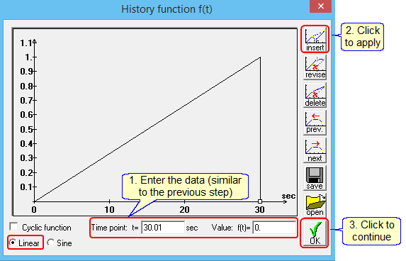
Click ![]() to continue.
to continue.
Define the damping: click on ![]() in the side menu
in the side menu
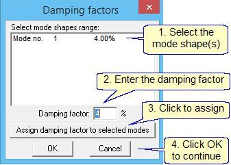
Display the results,
Natural frequency and period:
Click on ![]() in the side menu.
in the side menu.
Select ![]() in the menu.
in the menu.
The following table is displayed:
![]()
Displacements (graphic):
A time span must be defined before displaying the displacements. For example, display the deflections from 0 to 35 sec:
Click on ![]() in the side menu.
in the side menu.
Specify the result type, direction, and time span:
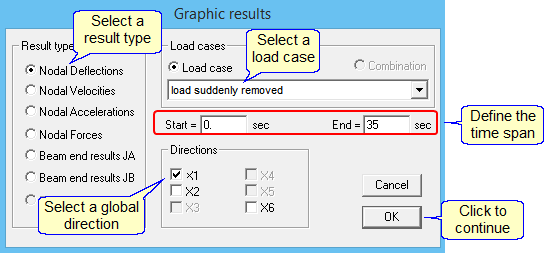
Select node 2. The program displays the time-deflection diagram:

Zoom in on the 30 to 35 sec range: ![]()
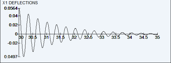
Note: The rate at which the displacements decrease is a function of the damping value.
Displacements (tables):
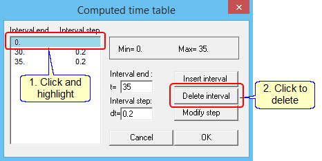
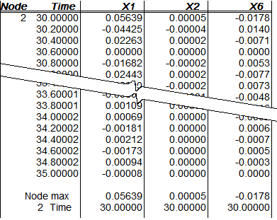
A time span must be defined before displaying the displacements. For example, display the deflections from 0 to 35 sec at node 2:
Select “Time tables” in the menu bar:


Repeat to add t = 35 sec, then delete t = 0 sec:
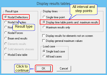
Click ![]() in the side menu.
in the side menu.
Select the result type, etc.:
The program displays the table:
Periodic forcing function
The following motor is located at node 5:
Weight = 40 kN.
Horizontal period force = 8.5 kN at a frequency = 1.75 Hz.
Damping ratio = 4%.
Select the ![]() option in the side menu and define an additional weight = 40 kN on node 5.
option in the side menu and define an additional weight = 40 kN on node 5.
Select ![]() in the side menu to calculate the mode shapes.
in the side menu to calculate the mode shapes.
Click on ![]() in the menu bar.
in the menu bar.
Click on ![]() in the side menu
in the side menu
Type in the name of the load case, e.g. “Periodic force”
Define a horizontal load of 8.5 kN at node 2.
Click on ![]() in the side menu
in the side menu
Enter the following history function (1.75 Hz = 0.5714 sec)
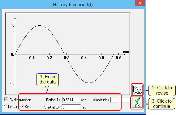
Click ![]() and display the results as described in the previous example.
and display the results as described in the previous example.
X1 deflections (graphic):

The deflections become stable after 7 sec.
the natural frequency:
![]()
Click on ![]() in the side menu.
in the side menu.
Click on ![]() in the side menu and revise the “Period T” to 0.454 sec (the natural frequency).
in the side menu and revise the “Period T” to 0.454 sec (the natural frequency).
The X1 deflections are:

The steady-state deflection is 59.4 mm.
The horizontal deflection for a model with a horizontal static load = 8.5 kn is 4.83 mm.
The Dynamic Load Factor (DLF) = 59.4/4.83 = 12.3.
Blast load
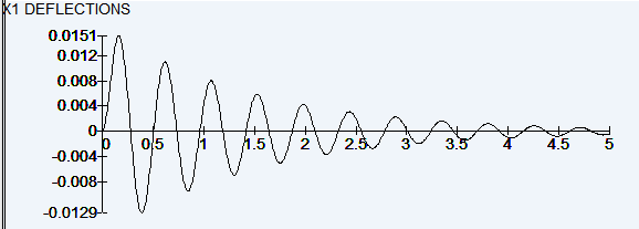
Calculate the deflections for a blast load of 30 kN that is applied at t =0 and decreases linearly to 0 kN ant t = 0.16 sec.
Click on ![]() in the side menu
in the side menu
Type in the name of the load case, e.g. “Blast load”
Define a horizontal load of 30 kN at node 2.
Click on ![]() in the side menu
in the side menu
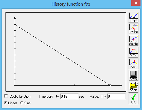
Enter the following history function (as described in the first example) by defining two points:
t=0, f(t) =1.0 and t=0.16, f(t)=0.
Click ![]() .
.
Click on ![]() in the side menu and define 5% damping.
in the side menu and define 5% damping.
Display the results as described in the previous examples.
X1 deflections (graphic):
Ground motion
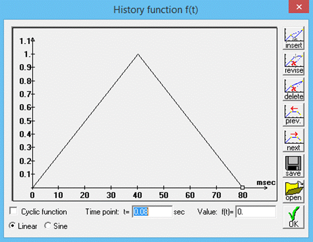
Calculate the deflections for a horizontal ground acceleration that increases linearly from 0 to 1.962 m/sec2 at 0.04 sec, then subsides linearly to 0 m/sec2 at 0.08 sec.
Click on ![]() in the side menu.
in the side menu.
Type in the name of the load case, e.g. “Ground motion”.
Click on ![]() in the side menu and define a magnitude = 0.2g (= 0.2×9.981 = 1.962 m/sec2).
in the side menu and define a magnitude = 0.2g (= 0.2×9.981 = 1.962 m/sec2).
Click on ![]() in the side menu.
in the side menu.
Enter the following history function (as described in the first example):
Click ![]() and display the results as described in the previous examples.
and display the results as described in the previous examples.
X1 deflections (graphic):

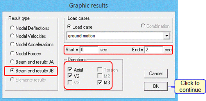
Display the forces and the moments at the top end of the left column as they vary in time.
Click on ![]() in the side menu and select the following options:
in the side menu and select the following options:
The program displays the results:
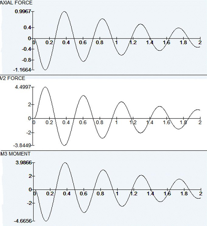
These results can be transferred to STRAP and added as load case results:
Click on ![]() in the main side menu
in the main side menu
Select the following options:
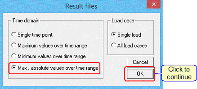
Select the “Ground motion” load case.
Return to the STRAP results module and display the graphic results for this load case. For example, moments:

