Abstract
This example demonstrates how to define a submodel and add it to the main model. Submodels are efficient when there is a portion of the structure that is repeated more than once in the model, e.g. the typical floor in a high-rise building. The advantages of the submodel are:
1. each submodel may contain up to 32,000 nodes, i.e. the total model sizes – comprised of the “main model” and all the submodels – is virtually unlimited.
2. When a submodel is revised each “instance” (occurrence) of the submodel in the structure is automatically revised.
3. The solution time is much faster than that required for an identical structure without submodels.
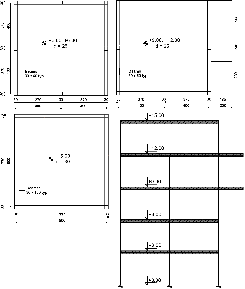
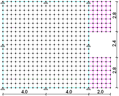
We will define the following structure:
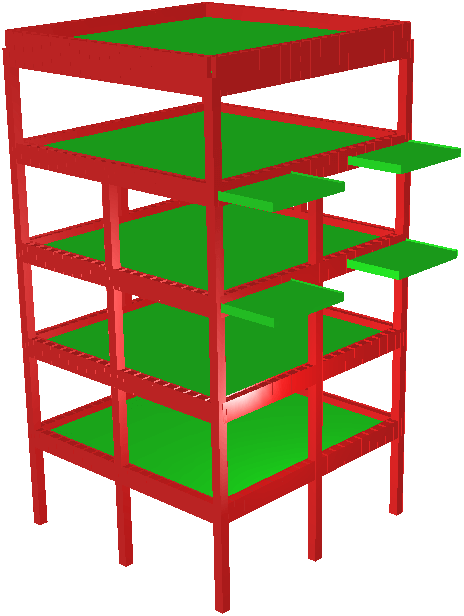
The structure consists of:
the “Main model” – the columns.
Three different submodels:
1. the two lower floors
2. the two upper floors (with the balconies)
2. the roof
Each of the first two submodels has two “instances”; the roof submodel has one instance.
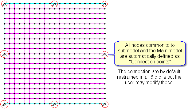
Each submodel instance is joined to the Main model at “connection points”.
Main model
click the ![]() new model icon.
new model icon.
select ![]() Space Frame and click
Space Frame and click ![]()
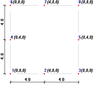
click ![]() in the side menu and define the following nodes:
in the side menu and define the following nodes:
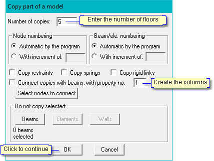
Copy the nodes to the other levels and create the columns:
select ![]() in the bottom side menu and then click on
in the bottom side menu and then click on ![]()
select all of the nodes.
select Node 1 as the reference node.
specify the new location of the reference node by coordinates;
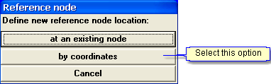
and enter the new coordinate value:
![]()
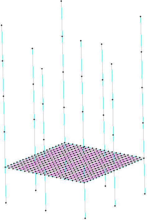
click ![]() in the icon bar to display an isometric view of the model.
in the icon bar to display an isometric view of the model.
Erase the four intermediate columns on the top floor:
click ![]() and then select
and then select ![]() in the side menu.
in the side menu.
select the four columns.
Define the floor slab at level +3.00:
display only the level at +3.00:
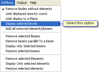
select “+3.00” in the list and click “OK”.
Click ![]() in the icon bar to cancel the isometric view.
in the icon bar to cancel the isometric view.
Click ![]() and then select
and then select ![]() in the side menu.
in the side menu.
Click “OK” in the following menu.
select the four corner nodes to define the floor contour and close by selecting the first node again.
Select “End contour definition”.
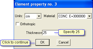
Click “OK” in the following menu to accept the default mesh parameters (check that Property 3 is specified ); the program creates and displays the floor slab.
Define the perimeter beams:
Click ![]() and then select
and then select ![]() in the side menu.
in the side menu.
![]()
Define the beams along the perimeter.
Display the entire model: Again select Remove and Display selected levels, but this time click on +3.00 in the list to remove the highlighting.
Click ![]() in the icon bar to display the isometric view of the model:
in the icon bar to display the isometric view of the model:
Define the beam and column sections:
click ![]() and then select
and then select ![]() in the side menu.
in the side menu.
click and highlight Property 1 in the table (the columns); click “Define/revise”, select ![]() and
and ![]() and define the section dimensions:
and define the section dimensions:
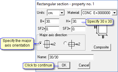
repeat for Property 2 (the beams) – 30 x 60 cm.
Click ![]() and then select
and then select ![]() in the side menu.
in the side menu.
Click and highlight Property 3 in the table (the floor slab); click “Define/revise”:
Define the supports:
click ![]() and then select
and then select ![]() in the side menu.
in the side menu.
select all nodes at level +0.00.
Submodels
Definition
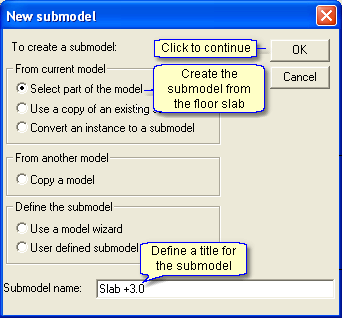
Create the first submodel from the floor slab at +3.00:
Click the ![]() icon to display the X1-X3 plane on the screen.
icon to display the X1-X3 plane on the screen.
Click ![]() in the side menu:
in the side menu:
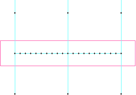
Select all the nodes at the floor level (use the Select by window option):
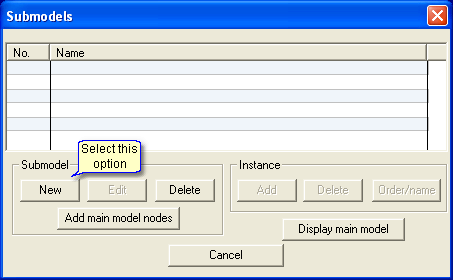
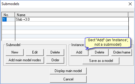
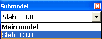
The program now displays a list of all submodels and instances in the side menu:
![]()
This list is displayed in all program modules (geometry, loads, results, etc) and is used to transfer from one submodel to another.
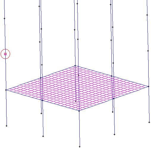
select the submodel from the list; the program displays it on the screen:
Create the second instance of the submodel:
select “Main model” in the submodel list.
click ![]() in the icon bar to restore the isometric view of the model.
in the icon bar to restore the isometric view of the model.
click ![]() in the side menu:
in the side menu:
Select the lower-left corner of the submodel as the “reference point”
Select the location of the reference point in the Main model:
Create the submodel at +9.00:
The second submodel is identical to the first one with the addition of the balconies. We will create it by copying and modifying the first submodel.
click ![]() in the side menu:
in the side menu:
Click “New” (submodel) in the following menu and – select ![]() Use a copy of an existing submodel and define the submodel name as “Slab +9.00”.
Use a copy of an existing submodel and define the submodel name as “Slab +9.00”.
Select Slab +3.00 from the list of existing submodels. The program displays the submodel; add the balcony elements as shown:
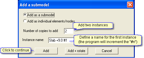
Add both instances of the second submodel:
click ![]() in the side menu:
in the side menu:
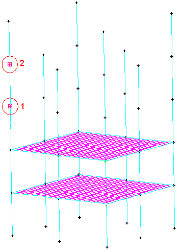
Select Slab +9.00 in the submodel list and click “Add” (instance).
select the lower-left corner of the submodel as the “reference point”. The program then displays the Main model; select the two reference points defining the location of the two instances of the submodel:
Define the third submodel at +15.00:
The roof slab is identical to the first submodel but with different slab and beam dimensions. There are also different connection points because not all of the columns go up to the roof.
Click ![]() in the side menu:
in the side menu:
Click “New” (submodel) in the following menu and –
Select ![]() Use a copy of an existing submodel and define the submodel name as “Slab +15.00”.
Use a copy of an existing submodel and define the submodel name as “Slab +15.00”.
Select Slab +3.00 from the list of existing submodels.
The program creates and displays the submodel.
Revise the geometry as follows:
Click ![]() and then select
and then select ![]() in the side menu.
in the side menu.
Click and highlight Property 4 in the table; click”Define/revise”, select ![]() and
and ![]() and define the section dimensions: 30 x 100. Assign this property to all beams in the submodel.
and define the section dimensions: 30 x 100. Assign this property to all beams in the submodel.
Click ![]() and then select
and then select ![]() in the side menu.
in the side menu.
Click and highlight Property 5 in the table 5; click “Define/revise” and define the slab thickness: 30 cm. Assign this property to all elements in the submodel.
Remove the unnecessary connection points (note that connection points without an exact corresponding Main model node are automatically connected by Rigid links to the closest Main model node).
Select ![]() in the side menu and click on
in the side menu and click on ![]()
select the four intermediate connection points.
The program assumes by default rigid connections between the submodel and the main model.
Assume that the roof beams are pinned to the columns, i.e. release the rotational degrees-of-freedom at the connection points:
select ![]() in the side menu and click on
in the side menu and click on ![]()
select the four corner connection points.
Add the third submodel to the structure:
Click ![]() in the side menu.
in the side menu.
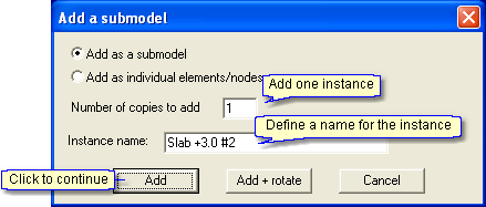
Select 3 Slab +15.00 in the submodel list and click “Add” (instance).
Specify 1 copy and define the instance name.
select the lower-left corner of the submodel as the “reference point”
the program then displays the Main model; select the top of the lower-left column as the location of the reference point in the Main model.
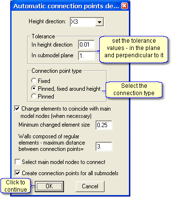
Connection points – additional options
There is an option to automatically define the connection points for a submodel to the main model. The program searches for Main model nodes that are within a “tolerance” distance of the selected submodel nodes.
Note: this option does not revise existing connection points. Connection points without an exact corresponding Main model node are automatically connected by Rigid links to the closest Main model node.
For example, use this option to redefine the connection points for the submodel Slab +3.00:
select the submodel in the small window:
Delete the existing connection points because the program will not revise them.
select ![]() in the side menu and click on
in the side menu and click on ![]()
select the four connection points.
click on ![]()
return to the Main model.
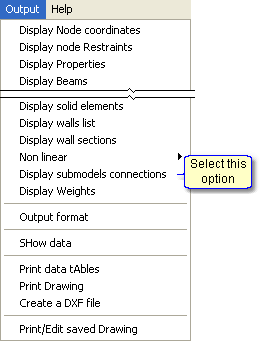
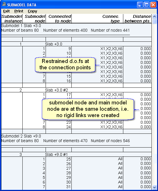
Submodels – tables
Display a table with the submodel data:
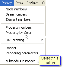
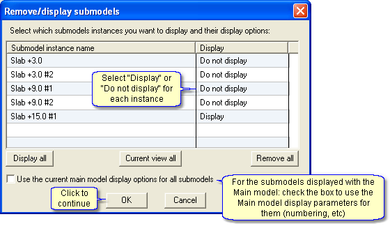
Submodels – display options
Selected submodels may be displayed/removed from the main model display. This option is useful when creating geometry or displaying the results.
Loads
Loads applied to a submodel may be applied to all instances or different loads may be defined for each instance of the submodel:
click the ![]() tab.
tab.
select ![]() in the side menu and enter a name for the load case.
in the side menu and enter a name for the load case.
select the Slab +3.00 in the small window.
select ![]() in the side menu.
in the side menu.
select ![]() and
and ![]() and define the loads:
and define the loads:
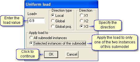
select the submodel instance:
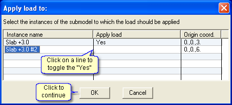
apply the load to the selected elements.
Continue to define loads, solve the model, and display the results.