Description
A round concrete pipe simply supported along its bottom edge only, is subjected to a vertical knife-edge load along the top edge line.
Geometry
Inner diameter: 0.6 [m]. Outer diameter: 0.8 [m]. Thickness: 0.2 [m].
E (elastic modulus) = 3,000,000 [t/m^2]
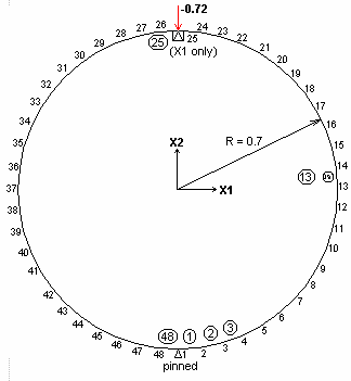
48 beam elements; Supports: pinned
Loads
Point load: FX2 = -0.72 at node 25.
Reference
Raymond J Roark, Roark’s Formulas for Stress and Strain, Fourth Edition. (Table VIII – Case 1, page 172), 1965 4th edition, McGraw – Hill book company.
Calculation
| +Mmax | = | 0.3183 WR | at x = 0 |
| -Mmax | = | -0.1817 WR | at x = p/2 |
Dy = -0.149ky (WR3/EI), where ky = 1.03833 for Ro/Ri = 1.3333.
Comparison of Results
| Node/beam | Result type | Result | Deviation | |||
| Theoretical | STRAP | |||||
| Node 25 | Deflection – X2 | 0.000191 | 0.000190 | 0.52% | ||
| Beam 25 | +Mmax | 0.08021 | 0.08010 | 0.12% | ||
| Beam 13 | -Mmax | -0.04579 | -0.04590 | 0.24% | ||