STRAP is a versatile solution for the design of a wide range of concrete and steel structures including residential/commercial buildings, bridges, industrial facilities, retaining tanks, communication towers, and many more. With a comprehensive workflow that covers the entire design process, STRAP’s reliable toolsets meet all the requirements needed for the analysis and design of a wide range of projects from a small scale plane frame structures to large scale hi-rise buildings. Various national design codes are available for the design of reinforced/prestressed concrete and hot-rolled/cold-formed steel. STRAP is multilingual and available in the following languages: English, Spanish, Chinese, Portuguese, Russian, Taiwan.
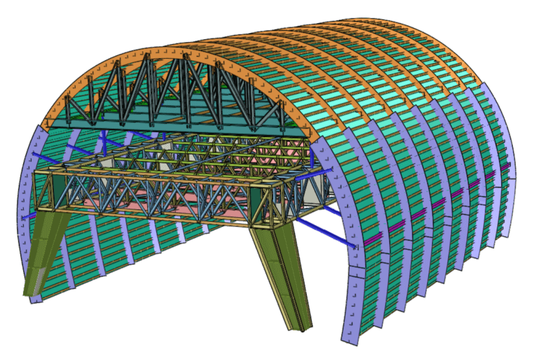
Intuitive node definition with a cartesian or cylindrical coordinate system. Various automated nodes generation options, including imported DXF files (CAD). Rigid-link or non-linear gap can be used to define non-conventional relationships between nodes.
Frames are modeled by beam elements (line elements) defined between two nodes, and can be oriented anywhere on the 3D space. Six degrees of freedom allowing both translation and rotation. Beam-column formulation which includes the effects of Axial deformation, biaxial bending, biaxial shear deformations, and torsion. STRAP has a built-in library of steel sections properties for different regions around the world. Ordinary shape, user-defined hot-rolled or cold-formed steel sections properties is feasible via STABLE module. Common shape sections properties can be defined by dimensions for concrete or welded steel. CROSEC add-on provides STRAP users the maximum flexibility by allowing them to define arbitrary shaped sections for concrete, hot-rolled steel, and cold-formed steel. Non-linear cable properties can be assigned to catenary the behavior of slender cables under their own self-weight.
Plate elements are three or four node 2D planar that can be oriented anywhere on the 3D space, usually used for modeling constructive surfaces such as slabs, footings, shear walls, retaining walls, etc. All translation degrees of freedom are available, as well as rotational degrees of freedom that are not out of plane. Powerful generation and control of rectangular, skewed, and circular meshing. Elements properties include flat, tapered, ribs, voids, or waffle. Orthotropic behavior is available as well.
Solid elements are three-dimensional stress elements, with actual thickness defined by the distance between four to eight end nodes. The element result types are stresses and principal stresses at the corner nodes.
Wall elements are used for modeling reinforced concrete shear/ductile walls. Advanced “design unit” feature enables separate design units in a single wall section for maximum design flexibility.
The Slab element is a more powerful and extended version of the Element-Mesh option. The Slab element automatically generates both the elements and the nodes within a user-defined area.
Cable element is a nonlinear element used to model the catenary behavior of slender cables under their own self-weight. Tension-stiffening and large deflection nonlinearity are inherently included in the formulation.
STRAP will automatically generate wind and seismic loads according to many design codes. Additionally, a sophisticated moving load generator allows the user to apply moving loads on frame and shell elements. Automatically generated Chess loading for beam elements.
Available Codes for wind loads: ASCE (USA), EC1 (EU), SP20.1330 (Russia), IS875 (India), AS/NZS1170, IS414 (Israel).
Available Codes for seismic loads: ASCE (USA), EC8 (EU), UBC, NBC (Canada), P100-1 (Romania), IS413 (Israel).
Define specific loads such as Force and moment on beams/elements. Temperature load (axial or gradient) for beams or elements. Additionally, STRAP presents a powerful user defined global load. Global load can be defined by coordinates anywhere in the model, the user then decides how to distribute the load. For example, a unidirectional area load.
Support displacements may be entered in the direction of any restrained degree-of-freedom, including rotation.
STRAP solvers have been tested by industry professionals for more than 35 years. Extremely fast analysis time can be achieved by utilizing quad core, 64-bit processors.
STRAP is capable of performing both linear static analysis, as well as, multi-step static analysis. linear static analysis engage a solution of a model with linear equations represented by K*U=R, where K=stiffness matrix, U=displacement vector, and R=force vector. Multi-step analysis is performed for multi-stepped load patterns such as, moving loads, vehicle loads, etc. the program will automatically generate load cases for each pattern and apply the loads in sequence.
Modal analysis (eigenvector) is performed for analyzing and understanding the dynamic behavior of a STRAP model, by finding the natural vibration mode shapes and their natural frequency. The mode shapes are the basis for modal superposition in response spectrum and time history analysis.
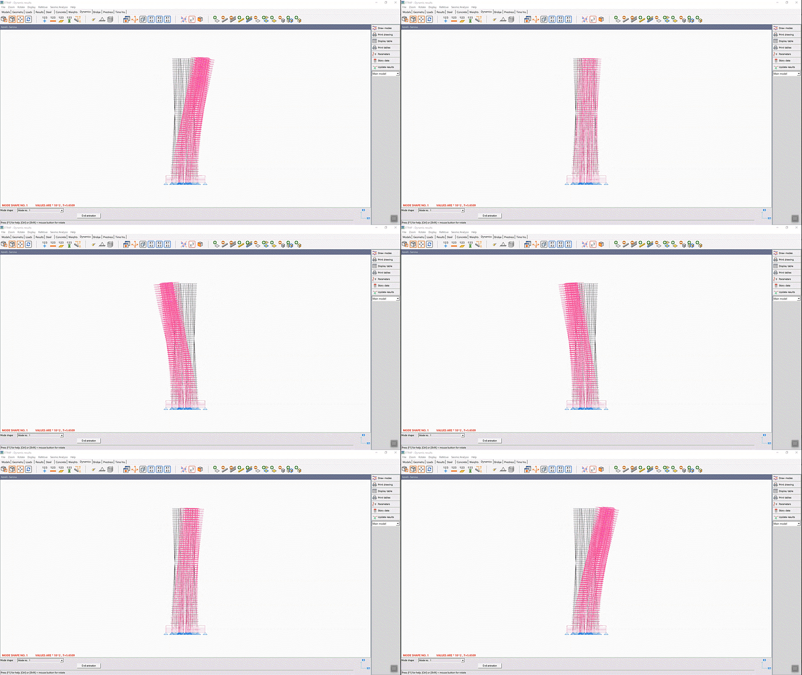
Response spectrum analysis determines the statistically likely response of a structure to seismic loading. The response spectrum can be defined based on code requirements or response spectra of recorded earthquakes. Response spectrum method of analysis is advantageous as it considers the frequency effects and provides a single suitable horizontal force for the design of structure.
Time-history analysis captures the step-by-step response of structures to loads that vary in time such as seismic ground motion, blast, machinery, wind, waves, etc. Time history analysis calculates the solution to the dynamic equilibrium equation for the structural behavior (displacement, member force etc.) at an arbitrary time using the dynamic properties of the structure and applied loading.
P-delta is a non-linear analysis that captures the effect of horizontal displacement and usually gravity load. P-delta calculations can be assigned to a single load case that can later be superimposed or a combination of load cases. P-delta effects are included only for beam (line) elements and are seamlessly integrated into analysis and design.
Slab deflection analysis calculates the slab deflections based on the effective moment-of-inertia including reinforcement, and the cracked section properties. This analysis accounts for long term effects such as creep, and presents results for immediate, long term or total deflections.
Most bridge design codes require that each point on the bridge be designed for the arrangement and combination of loads that produce the most adverse moments, shears, etc. at that point. In order to comply with the requirements of the code, STRAP’s bridge calculates influence lines for each result type (Moment, shear, reaction, etc.) at every point along the bridge. Lane loads include code/user defined vehicle loads, uniform load, and knife edge loads.
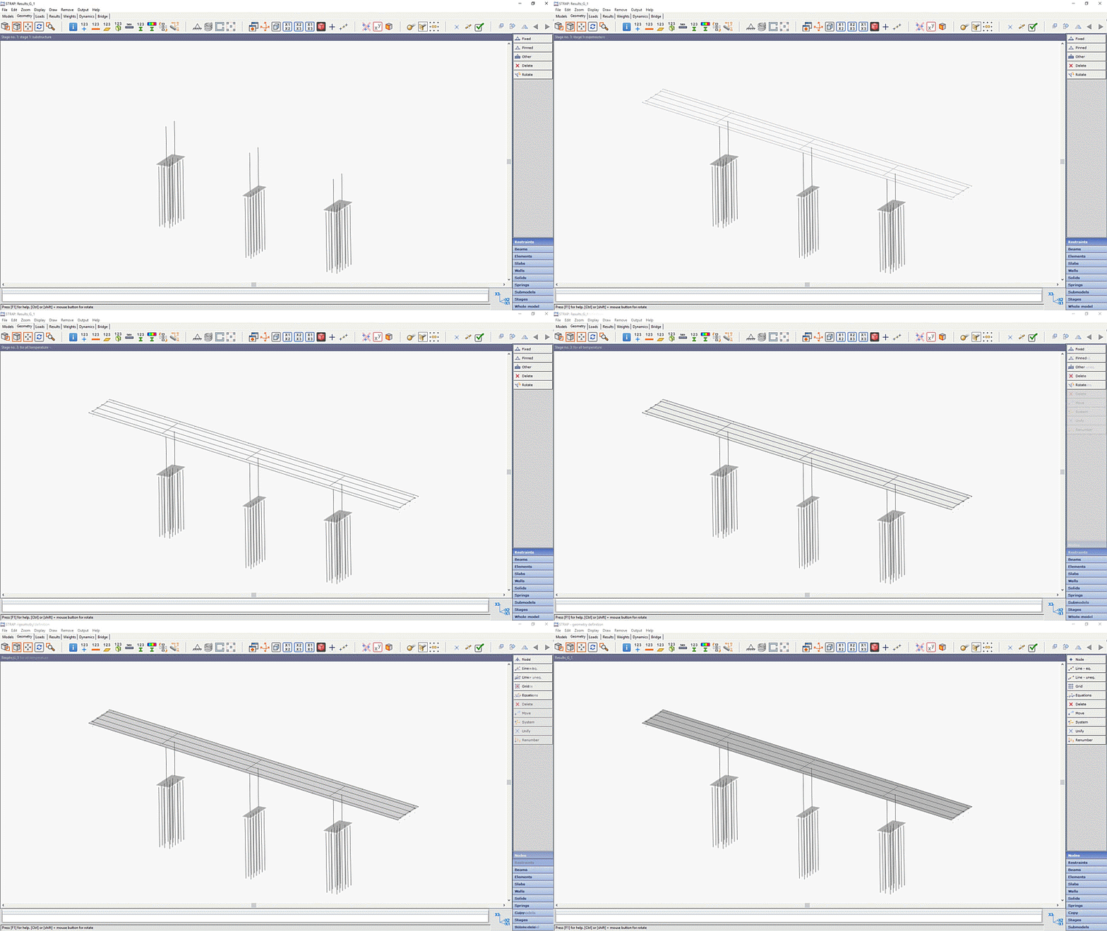
Staged construction analysis allows to define a sequence of stages wherein the user can revise the model’s geometry at each stage by deactivating/revising all modelling elements, supports, etc. Loads are applied selectively on each stage.
Graphic results are displayed on screen and include internal forces (moment,shear, axial, etc.), displacements, stresses, and reactions. For shell elements results can be displayed as a contour map, at element centers or “a long a line”. In addition to the ordinary analysis result types, STRAP also enables you to display results required for design, e.g. reinforcement area in concrete elements or design moments in slabs that account for the Mxy moments.
Design reinforced concrete frames, slabs, and walls according to code requirements (ULS/SLS) including: required area of main steel reinforcement, shear reinforcement, deflection, etc. Seismic design requirements are accounted for where applicable. Beam and column detailing are available, and can be assigned to layout for printing or exporting for a DXF file (CAD).
Available codes for reinforced concrete: ACI318 (USA), EC2 (EU), BS8110 (UK), NBR6118 (Brazil), CSA 23.3 (Canada), IS 456 (India), AS 3600 (Australia), SP 52-101 (Russia), IS466 (Israel).
Design prestressed concrete frames and slabs according to code requirements (ULS/SLS) including: cable losses, allowable stresses, ULS check for bending and shear, deflections, differential creep and shrinkage, and more. For prestressed frames, pre-tension and/or post-tension are available, and for slabs post-tension is available. Combining stage construction analysis and the prestressed module allows to analyze and design complicated structures.
Available codes for prestressed concrete: ACI318 (USA), AASHTO (USA), EC2 (EU), BS8110 (UK), BS5400 (UK), CSA23.3 (Canada), IS1343 (India), IRC18 (India), IS466(Israel).
Design hot-rolled, welded or cold-formed steel frames according to code requirements (ULS/SLS). Combined sections of any shape and form can be designed, as well as castellated/cellular members. STRAP can determine buckling/LTB effective length and deflection control length automatically or by user defined options. In addition, STRAP can perform optimization of steel sections based on analysis results or based on sway control. The optimization process helps to shorten the time of achieving economical and practical design. Composite steel/concrete Column or beams design are also available.
Available codes for hot-rolled/welded steel: AISC360-16-ASD/LRFD (USA), BS5950 (UK), CSA S16-14 (Canada), EC3 (EU), IS 800 (India), AS 4100 (Australia), SANS 10162 (South Africa), NBR 8800 (Brazil), GB 50017 (China), SP 16.13330 (Russia), IS1225 (Israel).
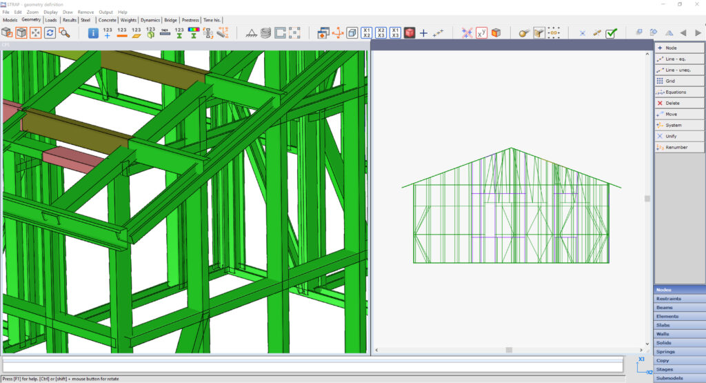 Available codes for cold-formed steel: AISI S100-16-ASD/LRFD (USA), BS5950 (UK), CSA S136 (Canada), EC3 (EU), AS 4600(Australia), GB 50018 (China).
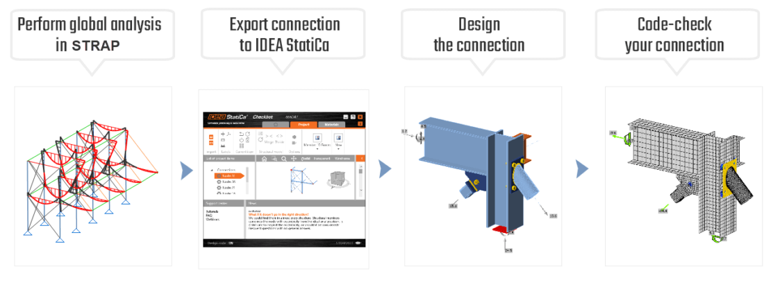
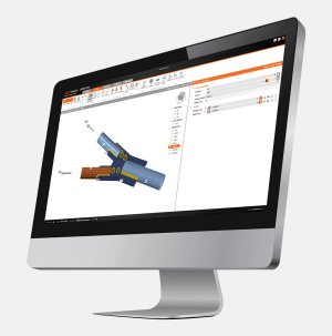
Connections are created, calculated and designed by partnering with IDEA StatiCa softwares such as IDEA StatiCa CheckBot and IDEA StatiCa Connections to manage and design the connections based on the structural model in STRAP. The IDEA StatiCa CheckBot is used as an overhead tool to manage and synchronize all connections provided by STRAP, and IDEA StatiCa Connection is used to construct the connections and Calculate them using CBFEM method, and also design the connections using several design codes
![]()
IDEA StatiCa is software for steel connection design for all types of welded and bolted structural steel connections and base plates. It fastens your connection design process by:
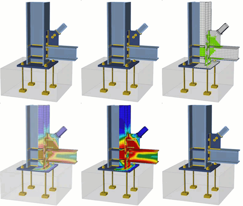
IDEA StatiCa was the first to combine the traditional Component method (equations) with FEM analysis. The new method is called Component-based Finite Element Method (CBFEM) and has been thoroughly tested in close cooperation with two technical universities and HILTI
With IDEA StatiCa licensing you have the ability to chose the best offer to fit your needs, chose the type of license, the version of the product and the duration of the license.
IDEA StatiCa offers useful information about the software throughout their website, here are some useful links
IDEA StatiCa support center offers a rich variety of textual and video content about all aspects of IDEA StatiCa Connection Design, including tutorials, simple project for practice, technical background, results verification and much more. Also you can sent a help request directly to IDEA StatiCa support team via online ticket.
Every student or teacher can apply for a FREE educational license of IDEA StatiCa for 12 months. The license has watermarks, limited report, and projects created in it are not compatible with commercial licenses. This license is neither for universities nor can be used commercially. Universities are required to purchase the Academic license.

Everything you need to know about IDEA StatiCa Connection in one single comprehensive course. Intended for all structural engineers and connection designers who wish to understand the principles of IDEA StatiCa and become immediately productive.
The trial license of IDEA StatiCa runs for 14 days, including:
Sign up to receive information about new releases, useful tips and special offers.