Abstract
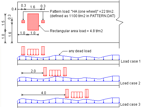
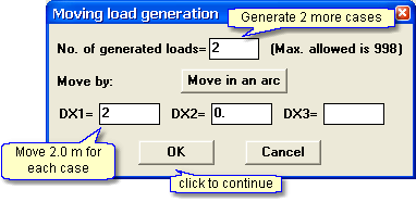
Use the Moving Load option to generate a series of load cases where the live load in each case is offset by a constant increment relative to the previous case. Note that the Moving Load option applies only to loads defined as Global Loads. The Figure below shows an arbitrary element grid for which three load cases must be defined. In all three cases, the loads are identical, but the live load in each case is offset 2.0 m from the live loads in the previous case.
Two types of Global Loads are defined:
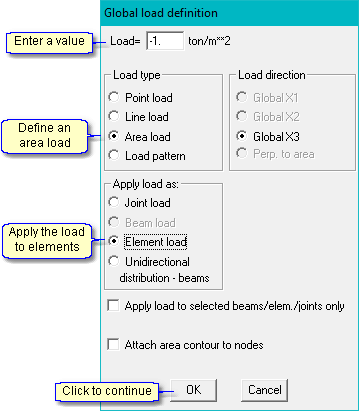
- pressure on a rectangular area defined by the user.
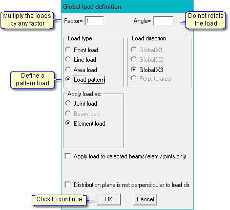
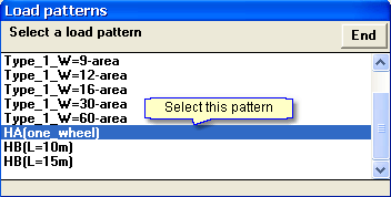
- pressure on a rectangular area retrieved from the “Pattern’ file.
Geometry Definition
- Click new model
 in the toolbar
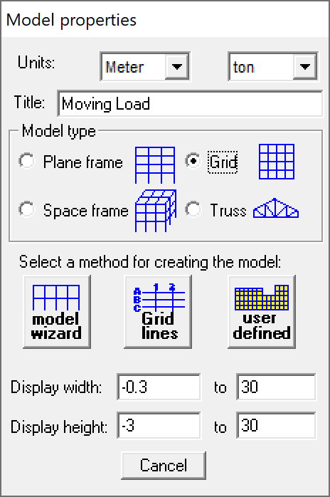
 - Set the default units to Meter & Ton, Model Type to
 Grid, and click the
  icon
icon
Model wizard
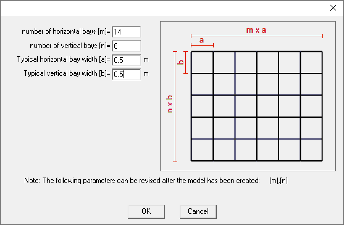
- Click the “Grid with elements” button
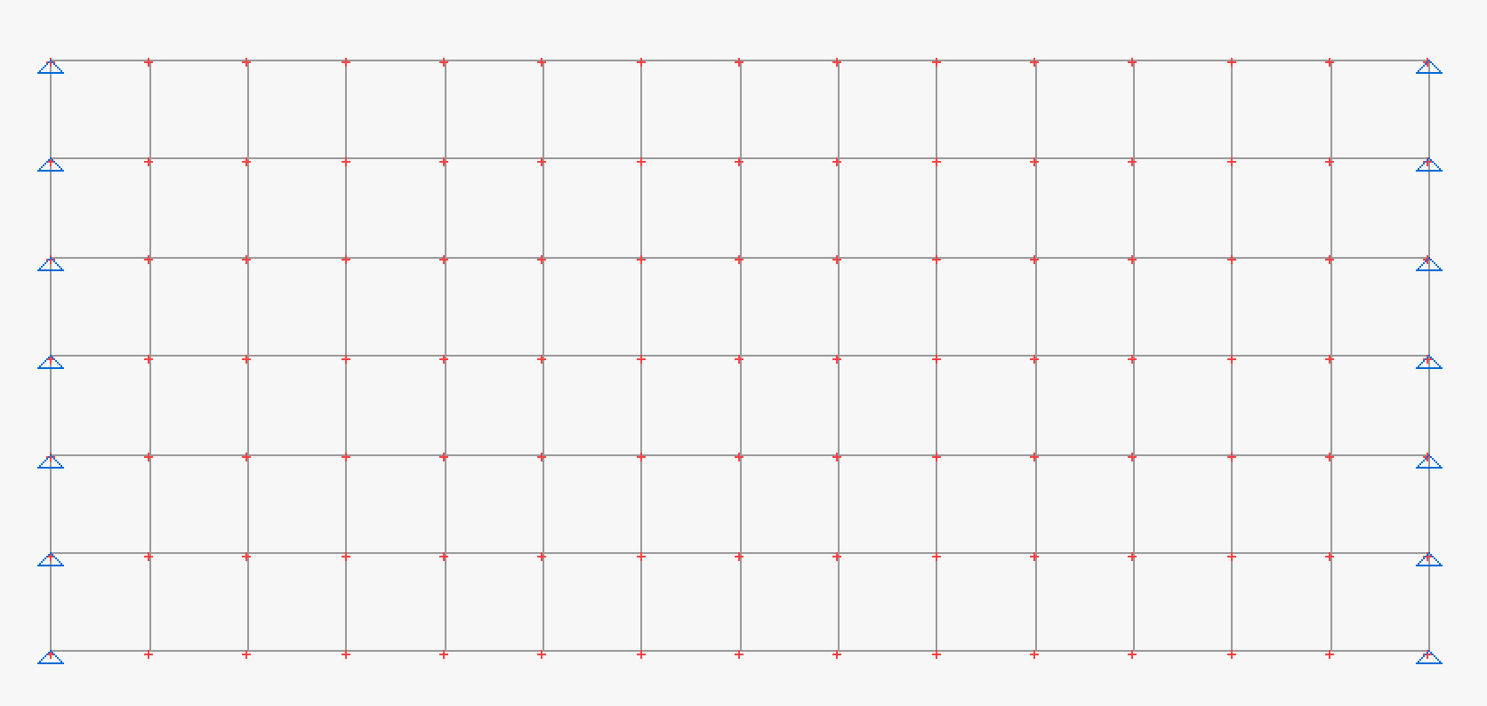
- Define a 3m x 7m (minimum) plane grid of elements
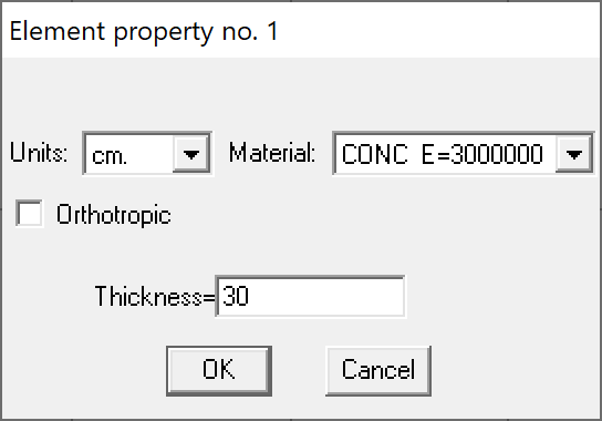
- Define the elements property:
- Material – Concrete
- Thickness – 30cm
STRAP
- Define pinned supports at the nodes as shown in the following drawing:
Loads Definition
- Click the
 tab
tab - Select
 and enter the load case title “Wheel”.
 - Select
 and select
- Define the load parameters as follows:
- Define the load location by coordinates:

- Define the lower-left corner of the rectangle:
![]()
- Similarly, define corners at (2.0, 1.0), (2.0,2.5) and (1.0,2.5).
- Move the cursor to the first corner (0.,0.) and click the mouse to close the rectangle; the program displays the load:

- Define the “Pattern” load. Select
 and select
- Define the pattern load parameters as follows:
- Select the pattern:
- Locate the pattern on the drawing:
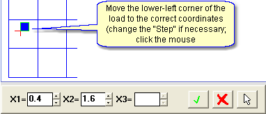
- Repeat for the second wheel load and place the pattern load at X1=2.3m and X2=1.6m.
- Select

- Select
 and select the load case just defined named “Wheel”.
 - Define the moving load parameters as follows:
- Click End in the load case list.
- To check that the cases were generated, select
 ; the load case list displayed is:
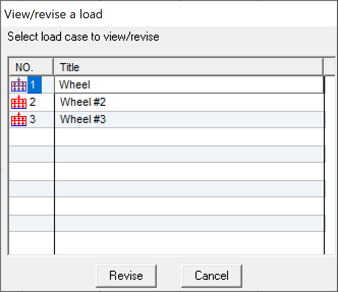
* Note that all three load cases contain the dead loads.
