Abstract
STRAP calculates the linear elastic deflection of a concrete slab based on the gross cross-section moment-of-inertia. However, the actual slab deflections are much greater due to several important factors:
- cracking.
- reinforcement ratio.
- time-dependent non-linear factors, such as creep and shrinkage.
The STRAP results module has an option to calculate the deflection using a method that takes into account these factors. The method is an empirical one based on an “effective” moment-of-inertia approach and it is important to understand that this method is not an exact one.
The method calculates an “effective” (reduced) moment-of-inertia that is a function of the ratio of the actual moment to the cracking moment of the element.
Eurocode 2:
![]()
ACI 318:
![]()
where the fourth power is used as suggested by Branson for continuous integration.
for both codes:
Ie = effective moment-of-inertia.
Ig = gross moment-of-inertia, including reinforcement.
Icr = cracked moment-of-inertia.
M = service moment.
Mcr = cracking moment
STRAP calculates the effective moment-of-inertia and for each element in both directions and then solves the model again using the reduced stiffness values.
The total deflection at is the sum of the immediate deflection ai from all service loads and the long-term deflection at from the sustained service loads, therefore different stiffness values are used for immediate and long-term deflection calculations based on the value of M derived from the loads applied; the user must define different load combinations for immediate and long-term loads.
The slab deflections will be calculated according to Eurocode 2.
Geometry Definition
New model:
- click the
 new model icon.
 - select
 and click
Nodes:
define the eleven corner nodes that form the slab contour:
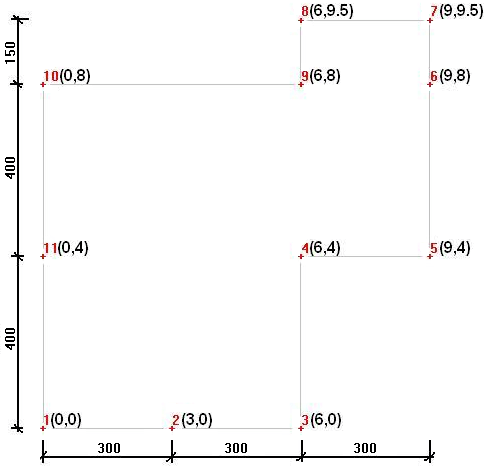
Elements:
- click
 and then select
  in the side menu.
 - click OK in the following menu.
- select the eleven corner nodes (in the order they are numbered) to define the floor contour and close by selecting the first node again.
- select End contour definition.
- click OK in the following menu to accept the default mesh parameters; the program creates and displays the floor slab.
- click
 in the side menu and click and highlight Property 1 in the table.
 - Define thickness = 200 mm and E = 30,000 mPa (30 x 106 kN/m2)
Restraints:
Define pinned supports at the nodes as shown in the following drawing:
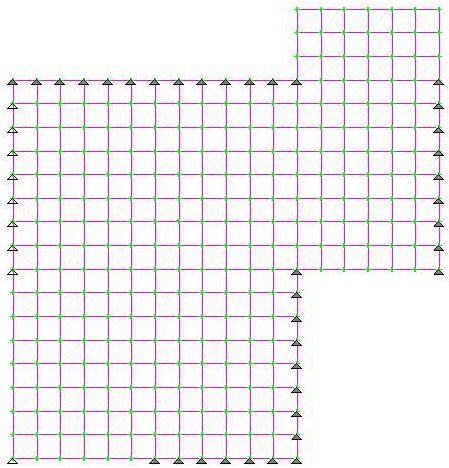
Loads Definition
- Define dead and live service loads in separate load cases:
- click
 at the top of the screen.
 - click
 and type in “Dead” as the load case title.
 - select
 in the side menu.
 - select
 and
and  and define a load = -10 kN/m2:
- select Select all elements.
- select
 .
. - repeat for a second load case titled “Live” with a uniform load = -3 kN/m2 applied to all elements.
- click
 to solve the model.
Results – Combination Definition
Three load combinations are required:
- ultimate loads – total – to calculate the reinforcement.
- service loads – total – to calculate the immediate deflection – ai.
- service loads – sustained – to calculate the long-term deflections. Assume that 30% of the live load is sustained.
To define the combinations:
- select
 in the side menu and
- define the following combinations:

Results – Elastic deflections
- click
 in the side menu and
- arrange the menu as follows, click OK.
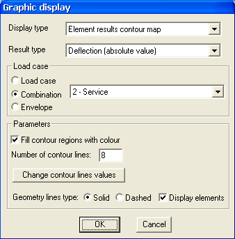
- the program displays the deflection contour map:
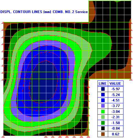
The maximum elastic deflection is 5.97 mm.
Results Deflections – cracked section & long term
- click
 in the side menu and
- specify the deflection parameters:
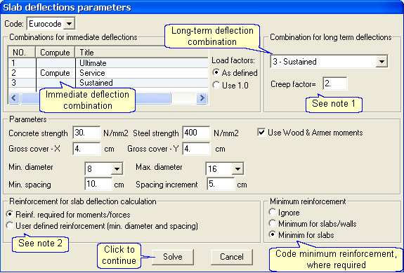
- Notes:
- The “creep factor” is used to calculate the total long-term deflection. The deflections calculated from the long-term combination using the effective moment-of inertia are multiplied by this factor. The factor corresponds to: Eurocode 2: Equation (7.20) & ACI 318: Equation (9-11).
- The reinforcement values used to calculated the effective moments-of-inertia are determined as follows:
 Reinf. required for moments/forces – The program calculates the area required and then selects actual reinforcement according to the specified range of diameters and spacings. This actual area is used to calculate the effective moments of inertia.
 User defined reinforcement – The program uses the spacing and diameter specified in the reinforcement option in this dialog box for all elements, top, and bottom, in both directions. However, different reinforcement areas may be defined for selected elements, as follows:
- select
 in the side menu
 - select

- select
- click Solve to calculate the reinforcement, the effective moments-of-inertia, and to solve the model again with the reduced stiffnesses.
- click
 and insert the following parameters:
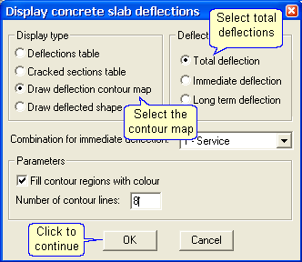
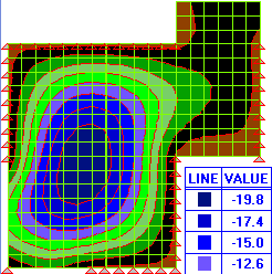
The maximum deflection is 19.8 mm, (19.8/5.97) = 3.3 times greater than the elastic deflection.
Results – Relative displacements
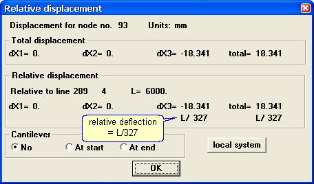
Estimate the deflection at node 93 in terms of L/x, relative to support nodes 289 and 4:
- click

- select
 Draw deflected shape and click OK; the program superimposes the deflected shape and deflection values:
- click Relative button at the bottom of the display.
- click on nodes 93, 289 and 4 (in that order). The program displays the relative deflection:
Results – Cracked section property table
- click

- select
 Cracked sections table and click OK; the program displays the following table:
where:
Elem = element number.
Comb = combination used for deflection calculation.
Dir = direction. Properties are calculated in both reinforcement directions.
Mcr = cracking moment.
M = moment at the element center.
F = The element axial force.
As = the tension reinforcement (calculated, minimum or user-defined).
As’ = the compression reinforcement (calculated, minimum or user-defined).
X = height of the compression block in the section.
Ir/Ig = ratio between the cracked and uncracked moments-of-inertia.
Ie/Ig = ratio between the effective and uncracked moments-of-inertia.
For example, in element 90
- the moment in the X-direction = 32.3 kN-m is greater than the cracking moment = 20.23 kN-m
- the section is cracked; hence the effective moment-of-inertia is 33.2% of the uncracked moment-of-inertia.
- in the Y-direction, the moment = 18.47 is less than the cracking moment, hence the program uses the uncracked section (Ie/Ig = 1.000)
